Contactor Interlock Wiring Diagram: Ensure Safety In Electrical Systems!
When it comes to electrical systems, safety should always be the top priority, and understanding the intricacies of contractor interlock wiring is essential for both professionals and DIY enthusiasts alike. A contractor interlock wiring diagram serves as a crucial blueprint that ensures the safe operation of dual power sources, such as a generator and the utility grid. By effectively managing the transfer of power, these diagrams not only prevent dangerous backfeeding but also protect your home and appliances from electrical surges. In this blog post, we'll delve into the importance of contractor interlock wiring, how to read these diagrams, and the steps you can take to ensure a safe and reliable electrical system.
Contactor Interlock Wiring Diagram
A contactor interlock wiring diagram is an essential tool for ensuring safety in electrical systems, particularly in applications where multiple circuits need to operate without interference. This diagram visually represents how contactors are wired together to prevent simultaneous operation, which could lead to equipment damage or hazardous situations. By following a well-structured interlock wiring diagram, electricians can create a fail-safe mechanism that ensures only one contactor is energized at a time, thus protecting both machinery and personnel. Understanding the intricacies of these diagrams not only enhances safety protocols but also streamlines the installation and maintenance processes, making it a vital resource for anyone working with electrical systems.
 in.pinterest.com
 Decoding The Interlock Circuit Diagram: Unraveling Its Secrets
Decoding the interlock circuit diagram is essential for anyone looking to ensure safety in electrical systems, particularly when dealing with contactor interlock wiring. Understanding the intricacies of these diagrams allows technicians and electricians to unravel the secrets behind how interlocks function to prevent simultaneous operation of equipment, which can lead to dangerous situations. By carefully analyzing the connections and components depicted in the diagram, one can identify the critical pathways that control the operation of multiple contactors, ensuring that safety mechanisms are in place. This knowledge not only enhances troubleshooting skills but also promotes a safer working environment by preventing electrical mishaps. Whether you're a seasoned professional or a novice, mastering the interlock circuit diagram is a vital step in safeguarding electrical systems.
 schempro.com
 Draeger Interlock Wiring Diagram At Gracessmitho Blog
In the realm of electrical safety, understanding the Draeger interlock wiring diagram is crucial for ensuring the proper functioning of your systems. At Gracessmitho blog, we delve into the intricacies of this wiring diagram, which serves as a vital component in preventing accidental operation of machinery. By following the Draeger interlock wiring diagram, technicians can effectively wire interlocks that safeguard against unintended activation, thus enhancing safety protocols in various applications. Our comprehensive guide not only simplifies the wiring process but also emphasizes the importance of adhering to safety standards, ensuring your electrical systems operate smoothly and securely.
 gracessmitho.blob.core.windows.net
 Contactor Interlock Wiring Diagram
A contactor interlock wiring diagram is an essential tool for ensuring safety in electrical systems, particularly in applications where multiple circuits need to operate without interference. This diagram visually represents how contactors are wired together to prevent simultaneous operation, which could lead to equipment damage or hazardous situations. By following a well-structured interlock wiring diagram, electricians can create a fail-safe mechanism that ensures only one contactor is energized at a time, thus protecting both machinery and personnel. Understanding the intricacies of these diagrams not only enhances safety protocols but also streamlines the installation and maintenance processes, making it a vital resource for anyone working with electrical systems.
 wiringdiagramall.blogspot.com
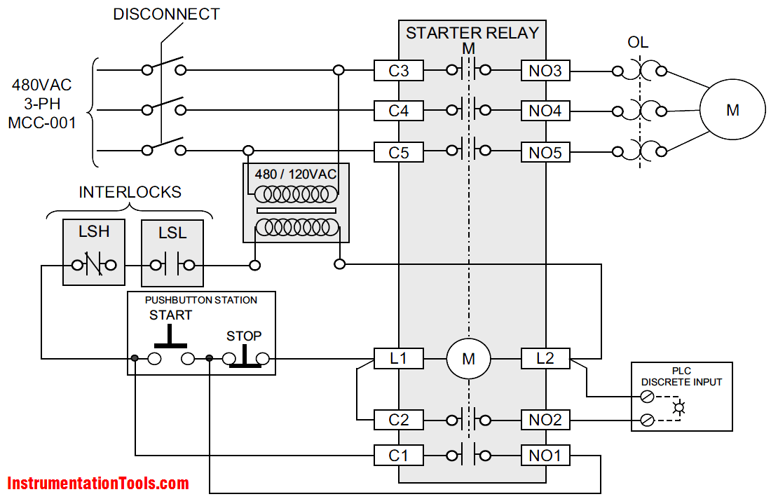
 Magnetic Contactor Interlock Wiring Diagram-motor Control Circuit
In electrical systems, a magnetic contactor interlock wiring diagram is crucial for ensuring safe and efficient motor control. This diagram illustrates how multiple contactors can be interconnected to prevent simultaneous operation of motors, which could lead to equipment damage or hazardous situations. By using interlock wiring, you can create a fail-safe mechanism that ensures only one motor operates at a time, providing a clear visual representation of connections and control logic. Understanding this wiring diagram is essential for electricians and engineers, as it not only enhances safety but also optimizes the performance of motor control circuits in various industrial applications. Whether you're setting up a new system or troubleshooting an existing one, mastering the magnetic contactor interlock wiring diagram is key to maintaining a reliable and secure electrical environment.
 www.youtube.com
 Other Wiring Gallery

www.electricianidea.com
Contactor Interlock Motor Connection

in.pinterest.com
Contactor Interlock Wiring Diagram For Motor Control
in.pinterest.com
Contactor Interlock Wiring Diagram

enginelistaiconvincing.z14.web.core.windows.net
Electrical Interlock Circuit Diagram

www.youtube.com
Interlocking Of Two Contactors Explained With Circuit Diagram
www.organised-sound.com
Electrical Interlock Circuit Diagram
wiringdiagramall.blogspot.com
Contactor Interlock Wiring Diagram
www.youtube.com
You Might Also Like: Cara Membuat Lampu Led Berjalan
Magnetic Contactor Interlock Wiring Diagram-motor Control Circuit